- 您现在的位置:买卖IC网 > Sheet目录179 > 2320241 (Phoenix Contact)UPS 24VDC 40A DIN RAIL
QUINT-UPS/ 24DC/ 24DC/40
10
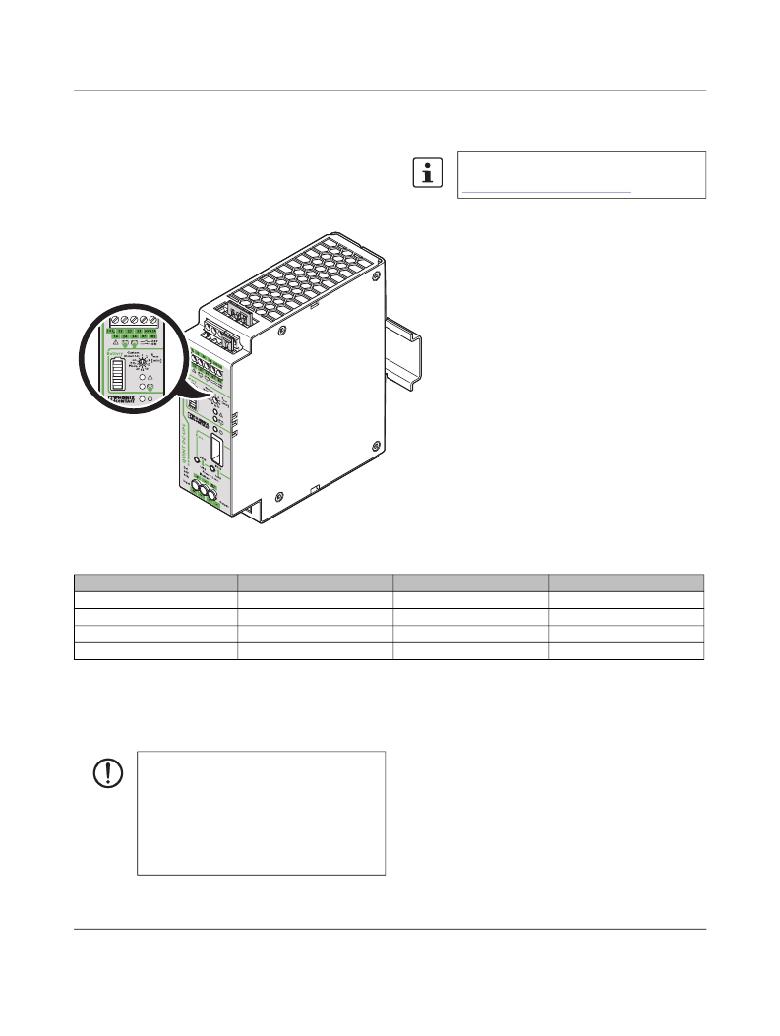
Signaling
Three LED indicators, an LED bar graph and three floating
relay contacts are available for function monitoring.
In addition, you can use the UPS-CONF configuration and
management software.
The software and the associated user manual
are available free of charge at
www.phoenixcontact.net/catalog .
Figure 13
Display elements
State
Power In OK, mains mode
Alarm
Battery mode
Battery charge
LED
Green
Red
Yellow
Bar graph
Switching output
-
13/14
23/24
33/34
Signal, default
-
Active low
Active high
Active high
Alarms, warnings and/or operating states can be individually
assigned to the battery mode and battery charge switching
outputs via the UPS-CONF configuration and management
software. Warnings are not indicated by the LED indicators.
ATTENTION:
LED indicator states are also simultaneously
signaled via the switching outputs in the default
settings. If an individual assignment of the
switching outputs takes place, signal states de-
viating from the LED indicators are possible.
Make sure that only sensible combinations are
signaled.
104660_en_01
PHOENIX CONTACT
18
发布紧急采购,3分钟左右您将得到回复。
相关PDF资料
232C,GY
BOX 4.38X3.25X2.00 9V GRAY
232I,GY
BOX 4.38X3.25X2.00 9V GRAY
232RC,GY
BOX 4.38X3.25X2.00 9V GRAY
233RI,GY
BOX 4.38X3.25X2.50 9V GRAY
236-6225-00-0602
SOCKET ZIP IN-LINE 36POS .1"
239-5605-02-0602
CONN SOCKET 39POS ZIP STRIP
2390
BOX ALUM COVR SZ-A BNC F-F BLUE
2391
BOX ALUM COVR SZ-A BNC M-F BLUE
相关代理商/技术参数
2320254
功能描述:UPS - 不间断电源 VRLA/24DC/1.3AH QUINT
RoHS:否 制造商:Phoenix Contact 功率额定值: 输出电压额定值:24 V 出口数量:2 运行时间(满载): 运行时间(半载):
2320267
制造商:Phoenix Contact 功能描述:UPS Power Supply 24DC/10/3,4AH
2320270
功能描述:DC/DC转换器 UPS/1AC/1AC/500VA QUINT
RoHS:否 制造商:Murata 产品: 输出功率: 输入电压范围:3.6 V to 5.5 V 输入电压(标称): 输出端数量:1 输出电压(通道 1):3.3 V 输出电流(通道 1):600 mA 输出电压(通道 2): 输出电流(通道 2): 安装风格:SMD/SMT 封装 / 箱体尺寸:
2320296
功能描述:电池组 UPS-BAT/VRLA/ 24DC/ 1.3AH
RoHS:否 制造商:Ultralife 电池大小: 电池数量: 输出电压:3.7 V 容量: 化学性质:Lithium 端接类型:Wire
2320-2G
制造商:Johanson Manufacturing 功能描述:VARIABLE CAPACITOR
2320-2GR1
制造商:Johanson Manufacturing 功能描述:VARIABLE CAPACITOR
23-202N
功能描述:LPH T-3-1/4 & T-5 WEDGE BASE SOC 制造商:visual communications company - vcc 系列:* 零件状态:在售 标准包装:100
2320-2R1
制造商:Johanson Manufacturing 功能描述:VARIABLE CAPACITOR